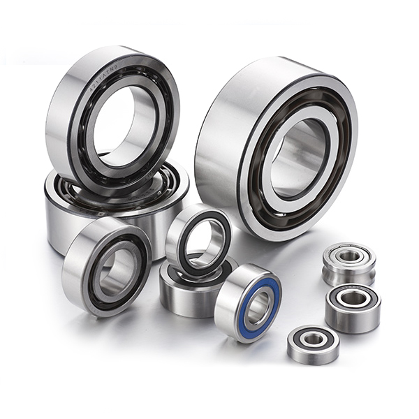
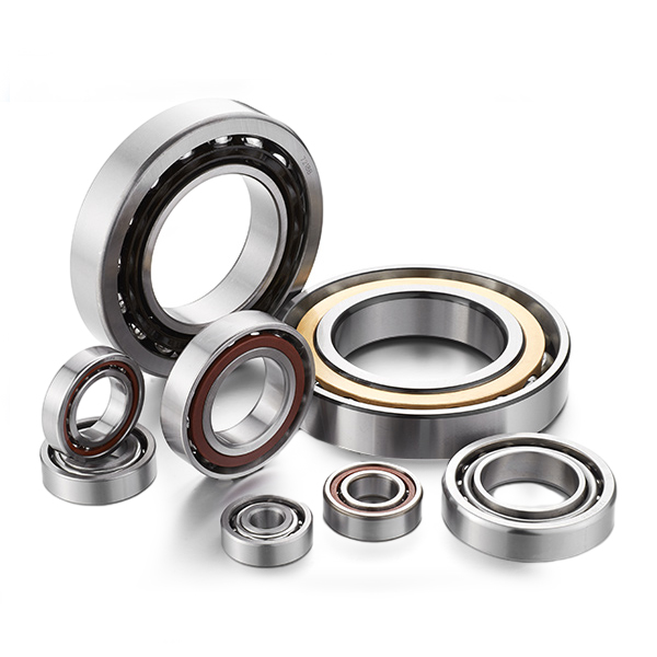
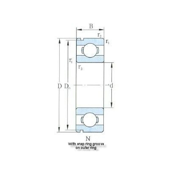
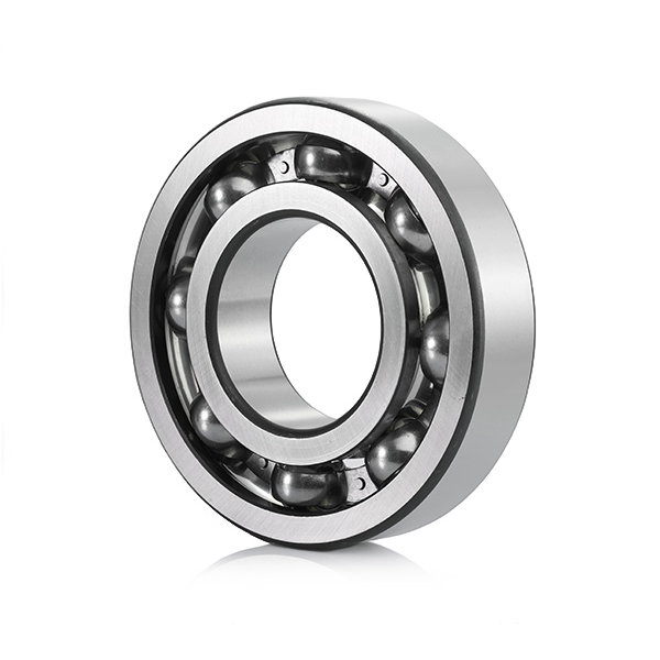
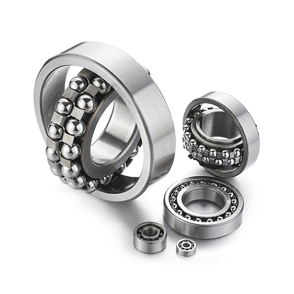
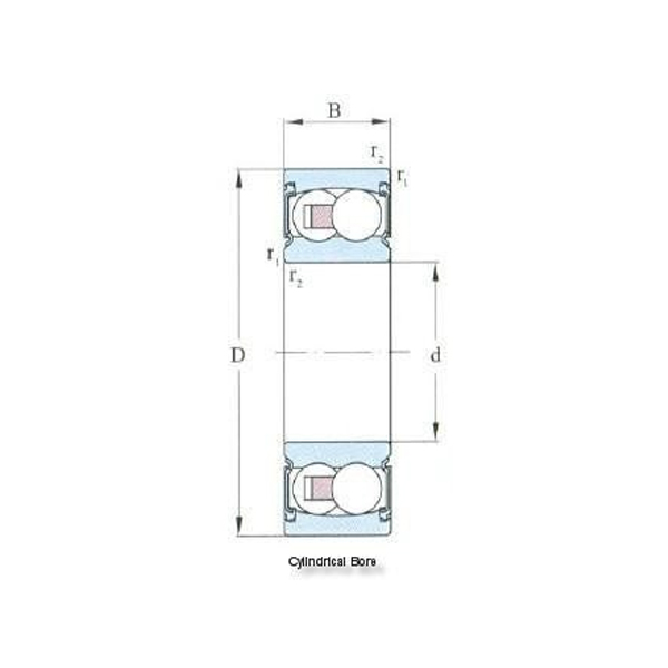
La decisión más importante en cualquier diseño de rodamiento de bolas de contacto angular no es el tamaño individual del rodamiento; es el arreglo. Ya sea que esté reconstruyendo el husillo de una máquina herramienta, especificando una caja de cambios o diseñando una bomba, la forma en que organiza los rodamientos controla la rigidez, el comportamiento térmico, la capacidad de carga axial e incluso la temperatura de funcionamiento. La regla estándar es simple: decida la disposición antes de calcular la vida útil del rodamiento.
Los rodamientos de bolas de contacto angular producen una fuerza axial cuando soportan una carga radial. Esto es un resultado directo del ángulo de contacto integrado en las pistas de rodadura. Por lo tanto, un solo rodamiento nunca funciona solo cuando el eje debe estar restringido en ambas direcciones. Necesita una disposición en pares, más comúnmente espalda con espalda (DB), cara a cara (DF) o tándem (DT), o una combinación de doble fila/precargada que se comporte como un solo paquete. Este artículo explica qué hace cada arreglo, por qué la precarga cambia los resultados y qué especificar al realizar el pedido.
En un rodamiento de bolas de contacto angular, la línea que conecta los puntos de contacto de la pista interior y exterior forma un ángulo con el plano radial. Los ángulos de contacto comunes son 15, 25 y 40 grados. Bajo una carga radial, el juego de bolas empuja el aro interior lateralmente en una dirección axial. Eso significa que un rodamiento de una sola hilera puede transmitir carga axial en una sola dirección. Si el eje soporta cargas axiales desde ambos lados, o si necesita un posicionamiento axial preciso, debe proporcionar un rodamiento de contrapeso. Ésa es la razón fundamental para utilizar un acuerdo.
El ángulo de contacto hace más que establecer la dirección de la carga. Un ángulo mayor proporciona una mayor capacidad de carga axial pero permite una menor capacidad de velocidad. Un ángulo más pequeño proporciona un mejor rendimiento a alta velocidad y menos rigidez axial. Su elección de acuerdo debe coincidir con esta compensación. Si desea comprender la mecánica subyacente, el artículo sobre Cómo se relaciona el ángulo de contacto con la capacidad de carga axial lo cubre en términos prácticos.
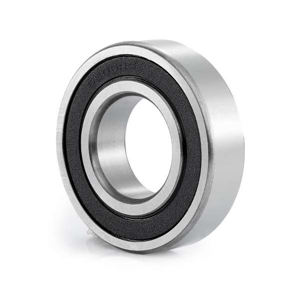
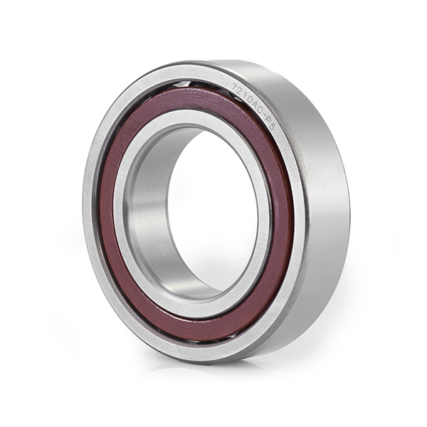
Un rodamiento de bolas de contacto angular de una hilera es el módulo básico de cada par. Si está creando arreglos personalizados, es la pieza más fácil de comprar, pero debe ser preciso en cuanto a la dirección del ángulo de contacto. Esa dirección está indicada por la orientación del rodamiento en el eje y en la carcasa; Voltear el rodamiento cambia la trayectoria de la carga axial.
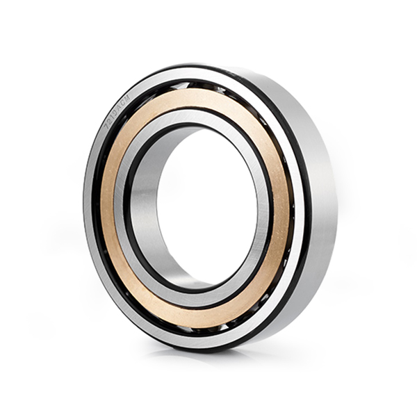 Rodamiento de bolas de contacto angular de una hilera para emparejamiento personalizado Este rodamiento de una sola hilera es la unidad fundamental para construir pares de contactos angulares. Su diseño de ángulo de contacto maneja cargas radiales y axiales unidireccionales, y la orientación precisa en el eje determina la trayectoria de la carga axial, lo que lo hace esencial para disposiciones personalizadas. Ver producto →
 Una vez que acepte que los rodamientos de contacto angular deben funcionar en pares, el siguiente paso es elegir la relación geométrica. Los fabricantes utilizan códigos de dos letras estampados en el rodamiento o en el espaciador del aro exterior: DB, DF y DT.
En una disposición espalda con espalda, las líneas de contacto divergen desde el centro del par de rodamientos. El punto de carga efectivo entre las dos filas es amplio, por lo que el par tiene una alta rigidez de inclinación. Es por eso que DB es la opción estándar para husillos de máquinas herramienta, ejes de alta precisión y cualquier aplicación donde se deba resistir una carga de momento. Una advertencia: la configuración DB es sensible a las diferencias de temperatura entre los anillos interior y exterior. Si el aro interior se calienta más que el aro exterior, la precarga tiende a aumentar.
En una disposición cara a cara, las líneas de contacto convergen hacia el centro del eje. El punto de carga efectivo es más estrecho, por lo que la rigidez de inclinación es menor que en DB. El conjunto DF es más tolerante con la desalineación del eje y la expansión térmica, y proporciona un diseño compacto y estable para ejes cortos. Lo verá utilizado en secciones de cajas de engranajes, tornillos de alimentación y casos donde la distancia entre las posiciones de los rodamientos es pequeña.
En una disposición en tándem, ambos rodamientos miran en la misma dirección. Las líneas de contacto son paralelas, por lo que el par comparte una carga axial pesada que actúa en una dirección. Los pares en tándem tienen una capacidad de carga axial en una dirección extremadamente alta, pero no estabilizan el eje en la dirección opuesta. Debes emparejar dos conjuntos en tándem uno detrás del otro o uno frente al otro para obtener control bidireccional. Una práctica común es utilizar dos rodamientos en tándem en un lado y un rodamiento en el otro, formando una disposición TBT o TFT.
| Arreglo | Patrón de línea de carga | Dirección de carga axial | Rigidez basculante | Uso típico |
|---|---|---|---|---|
| DB (espalda con espalda) | divergente | Ambas direcciones | Alto | Husillos de máquinas, ejes de precisión. |
| DF (presencial) | Convergiendo | Ambas direcciones | inferior | Ejes cortos, cajas de cambios. |
| DT (tándem) | paralelo | una dirección | No autónomo | Cargas axiales unidireccionales pesadas |
No todos los diseños necesitan un par de rodamientos de una sola hilera por separado. Dos opciones preensambladas pueden simplificar su vivienda y reducir el inventario.
Los rodamientos de bolas de contacto angular de dos hileras son esencialmente dos rodamientos de contacto angular de una hilera integrados en una unidad. La disposición interna normalmente es equivalente al emparejamiento DB, lo que proporciona una forma sencilla de obtener soporte axial bidireccional en una carcasa compacta. Series como las familias 30 y 38 son populares para maquinaria agrícola, reductores de engranajes, bombas y aplicaciones industriales en general. La principal desventaja es que no se puede ajustar la precarga de forma independiente; debes utilizar la precarga fijada por el fabricante. Si su diseño requiere una precarga personalizada o una velocidad muy alta, una disposición emparejada de una sola fila es más flexible.
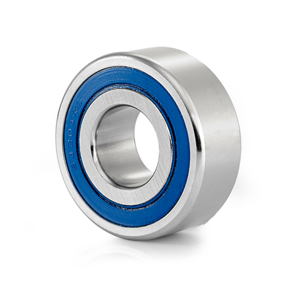 Rodamientos de bolas de contacto angular de doble hilera series 30 y 38 Estos rodamientos de doble hilera integran dos unidades de una sola hilera en una configuración similar a DB, ofreciendo soporte axial bidireccional en una carcasa compacta. Son adecuados para reductores y bombas, aunque la precarga la fija el fabricante y no es regulable. Ver producto →
 Un rodamiento de bolas de contacto de cuatro puntos es una forma compacta de soportar cargas radiales y cargas axiales en ambas direcciones en una sola unidad. Los anillos interior y exterior tienen pistas de rodadura cuyos puntos de contacto se alternan; las bolas hacen contacto con el aro interior en dos puntos y con el aro exterior en dos puntos. Esto funciona bien para aplicaciones dominadas por el empuje, como ganchos de grúa, mesas giratorias y bombas para automóviles, donde el espacio es reducido y las fuerzas axiales son mayores que las cargas de inclinación. Los rodamientos de cuatro puntos no suelen sustituir a un par DB cuando la prioridad es una alta rigidez radial, por lo que se debe comprobar cuidadosamente la envolvente de carga.
 Rodamiento de bolas de contacto de cuatro puntos para aplicaciones de empuje compactas Este rodamiento soporta cargas radiales y axiales desde ambas direcciones en una sola unidad a través de puntos de contacto alternos. Es compacto e ideal para usos dominados por el empuje, como ganchos de grúa y mesas giratorias, pero no se recomienda cuando la prioridad es una alta rigidez radial. Ver producto →
 Para husillos CNC y mecanizado pesado, es posible que un simple par de DB no proporcione suficiente rigidez axial. La forma de aumentar la rigidez es reemplazar un solo rodamiento en un lado por dos rodamientos montados en tándem. Esto es lo que describen códigos como TBT y TFT.
En una disposición TBT, se montan dos rodamientos en tándem espalda con espalda con un rodamiento. El par en tándem se opone a una dirección axial con doble capacidad, mientras que el rodamiento único proporciona la dirección opuesta. El resultado es una mayor rigidez axial en una dirección sin sacrificar la estabilidad en la otra. Si ambas direcciones axiales necesitan una gran rigidez, se pueden utilizar cuatro rodamientos: dos pares en tándem, dispuestos espalda con espalda o cara a cara. Códigos como QBC, QTC y QBT representan estas combinaciones de cuatro filas. Son comunes en aplicaciones aeroespaciales, de máquinas herramienta y rotativas de alta precisión.
Cada rodamiento adicional aumenta la rigidez axial total, pero también agrega costo, generación de calor y complejidad de montaje. Para la mayoría de las aplicaciones, es suficiente un par DB adaptado o un rodamiento de dos hileras.
La precarga es la carga axial aplicada al par de rodamientos antes de que arranque la máquina. Elimina el juego interno, amplía la zona de carga y mantiene los elementos rodantes en contacto continuo con las pistas de rodadura. Sin precarga, un rodamiento de contacto angular puede patinar, generar ruido y perder precisión de posicionamiento.
Hay dos familias de precarga: rígida y de resorte.
La precarga rígida, también llamada precarga posicional, se incorpora al par de rodamientos rectificando las caras del aro interior o exterior hasta lograr la diferencia de ancho correcta. Cuando aprieta la tuerca de montaje o la cubierta del extremo atornillada, los anillos se juntan y la precarga se fija. Esto proporciona la mayor rigidez posible para un grupo de rodamientos determinado. Los rodamientos emparejados logran esto rectificando las caras; Cuando un par está fabricado con rodamientos estándar, el diseñador puede insertar espaciadores interiores y exteriores de diferentes anchos para generar la misma precarga. El riesgo es que los cambios de temperatura, especialmente un delta entre los anillos interior y exterior, alteren la precarga. En un par de DB funcionando a alta velocidad, el crecimiento térmico puede aumentar la precarga y provocar acumulación de calor.
La precarga del resorte, a veces llamada precarga de presión constante, utiliza un conjunto de resortes detrás del anillo exterior para aplicar una fuerza axial fija. Se utiliza en husillos de alta velocidad o ejes con carga ligera donde el diseñador desea protección contra la expansión térmica. El resorte mantiene una fuerza axial predecible en un rango de temperaturas y desgaste menor, pero la rigidez del conjunto es menor que la de un par rígidamente precargado.
Cuando seleccione un grado de precarga, tenga en cuenta la velocidad de funcionamiento. Una precarga pesada aumenta la rigidez pero aumenta el par de fricción y la temperatura de funcionamiento; La precarga ligera es mejor para alta velocidad y baja temperatura, pero brinda menos soporte bajo cargas de corte pesadas. Si no está seguro, comience con un grado de precarga medio y valídelo mediante el aumento de temperatura durante una prueba.
La forma en que escribe las especificaciones de un rodamiento determina si recibirá una unidad utilizable o una caja de piezas atractivas pero incompatibles. Una serie de dimensiones por sí sola nunca es suficiente.
Desde el punto de vista de las adquisiciones, también vale la pena confirmar que la fábrica tiene un proceso de molienda controlado y registra los datos de medición. Es más probable que los rodamientos que provienen de una línea de producción con inspección automatizada y clasificación estandarizada mantengan una precarga constante. En muchas máquinas industriales, el lado fijo utiliza un par de rodamientos de contacto angular mientras que el lado libre utiliza rodamientos rígidos de bolas para permitir el desplazamiento axial. Asegúrese de que el diseñador del sistema haya considerado esa ruta de expansión térmica.
Elegir una disposición de rodamientos de contacto angular no consiste en memorizar códigos. Se trata de controlar la rigidez, la trayectoria de la carga axial, el crecimiento térmico y la velocidad. Comience con la disposición, agregue la precarga correcta y trate los pares coincidentes como unidades inseparables. Si hace eso, el rodamiento funcionará según lo diseñado. Si omite la decisión sobre la disposición, ninguna precisión de los rodamientos salvará al sistema de un calentamiento prematuro, vibración o falla prematura.

Derechos de autor © Ningbo Demy (D&M) Bearings Co., Ltd. Todos los derechos reservados.
 Fabricantes de rodamientos industriales OEM/ODM

 Buscar
 ES
ES English
 Español